ADONIS Main Features

The ADONIS user interface provides a complete interactive modeling environment, project management facilities, a built-in library of materials, easy specification of boundary conditions and structural elements, extensive plotting capabilities and run-time monitoring of results.
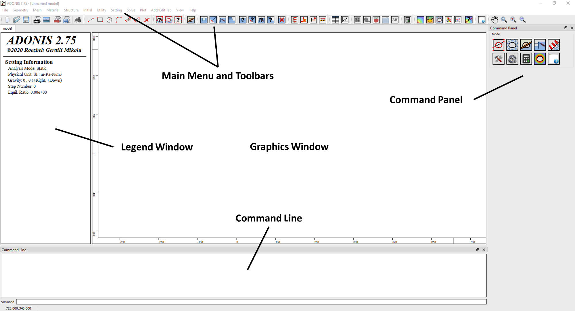
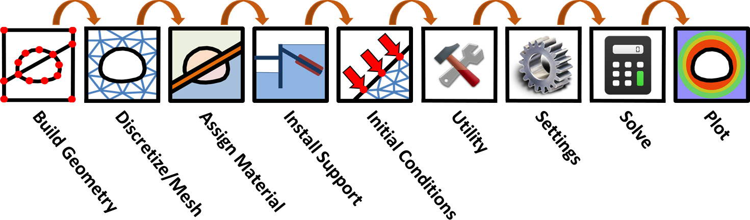
Workflow
ADONIS user interface designed to assist with the logical process of model creation, starting with Geometry (boundaries) and progressing through the various modeling features (Meshing, Support, Groundwater, Loads).
The first step in creating a ADONIS model is to create the boundaries defining the model.
 |
Use this tool to create line segment. Mouse or enter coordinates in the Command Panel can be used. |
 |
Use this tool to create rectangular shapes from two diagonally opposite corners. |
 |
This tool lets you create circles with a given center and radius. |
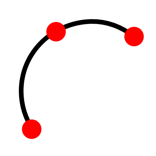 |
If you know the start-point, the end-point and a point in the middle on the arc line, you can use this tool to create arcs. |
 |
This tool lets you create interface boundary to the model. |
 |
Individual Crack can be used to separate elements and nodes along its boundary. This could be useful when trying to use embedded beam element sandwiched between two interfaces. |
 |
This tool lets you to remove the line segment. |
Import DXF
Boundaries , bolts and polyline or polygon drawing tools can be imported into ADONIS from a DXF file (AutoCAD Drawing Exchange File), using the Import DXF option in the Import sub-menu of the File menu. This allows users to import drawings created in AutoCAD, for example, into ADONIS.
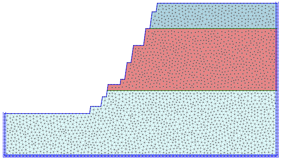
Discretize and Mesh
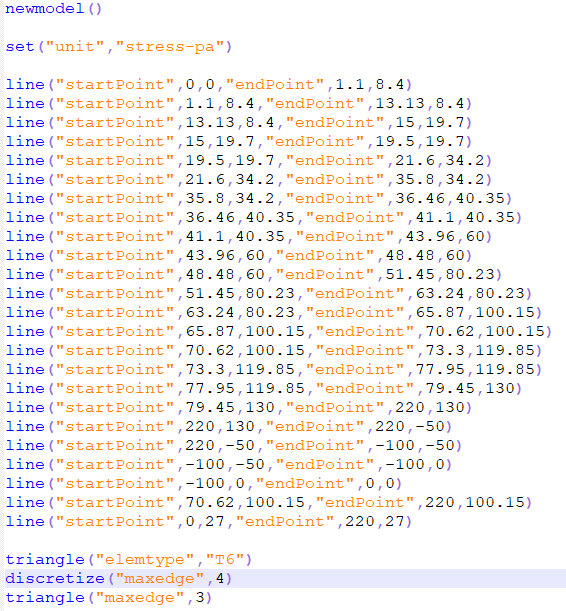
The finite element mesh can be created. ADONIS incorporates an open-source state-of-the-art two-dimensional automatic finite element mesh generator (i.e. triangle), which can generate triangular finite element meshes. The advanced meshing algorithm used in ADONIS simplifies the task of mesh generation for the user - a high quality mesh can be generated with just one mouse click. To give the user maximum flexibility in defining the mesh, the mesh generation procedure consists of two general steps: 1) Discretization 2) Meshing. The main parameters controlling the discretization and meshing, are found in the Command Panel (e.g. mesh type, edge and element sizes).
Constitutive Material Models
The constitutive models provided in ADONIS are arranged into elastic and plastic model groups. Input parameters to all of these built-in models can be entered directly as commands, interactively using the GUI or controlled via JavaScript to modify the behavior of the models.
IsoElastic: Provides the simplest representation of material behavior. This model is valid for homogeneous, isotropic, continuous materials that exhibit linear stress-strain behavior with no hysteresis on unloading.
Mohr-Coulomb: The conventional model used to represent shear failure in soils and rocks.
Strain-Hardening/Softening: Allows representation of nonlinear material softening and hardening behavior based on prescribed variations of the Mohr-Coulomb model properties (cohesion, friction, dilation and tensile strength) as functions of the deviatoric plastic strain.
Modified Cam-Clay: Used to represent materials when the influence of volume change on bulk property and resistance to shear need to be taken into consideration, as in the case of soft clay.
Hoek-Brown: Characterizes the stress conditions that lead to failure in intact rock and rock masses. The failure surface is nonlinear, and is based on the relation between the major and minor principal stresses. The model incorporates a plasticity flow rule that varies as a function of the confining stress level.
Modified Hoek-Brown: Provides an alternative to the Hoek-Brown model with a stress-dependent plastic flow rule, described above. The modified model characterizes post-failure plastic flow by simple flow rule choices given in terms of a user-specified dilation angle. This model also contains a tensile strength limit similar to that used by the Mohr-Coulomb model. In addition, a factor-of-safety calculation based on the shear-strength reduction method can be run with the modified Hoek-Brown model.
Plastic Hardening: Plastic Hardening model takes to account the strain-dependency of the modulus. At low strain levels most soils exhibit a higher stiffness than at engineering strain levels, and this stiffness varies non-linearly with strain. The option of small-strain stiffness is also available (flag_small = 1). Plastic Hardening model assumes an elastic material behavior during unloading and reloading for very small strains, with the small-strain option activated soil stiffness behaves nonlinearly with increasing strains.
Ubiquitous-Joint: The ubiquitous-joint model is an anisotropic plasticity model that includes weak planes of specific orientation embedded in a Mohr-Coulomb solid.
User-Defined Constitutive Models: From Version 2.5.5 forward of ADONIS, users can define their own constitutive model and integrate the model into the program by using a dynamic-linking library (dll). The dll needs to be placed in the installation folder of the program. The program will then detect and load the dll. One or more materials can be included in the dll. Couple of examples are included in the UDCM folder in the ADONIS installation folder.
Interface Constitutive Models
There are currently two standard joint behavior models available for ADONIS.
Glued Interfaces: If interfaces are declared glued, no slip or opening is allowed, but elastic displacement still occurs, according to the given stiffnesses.
Coulomb Shear-Strength: The Coulomb shear-strength criterion limits the shear force by the relation:
Fsmax = cL + tanφ Fn
where c = cohesion (in stress units) along the interface, L = effective contact length, and φ = friction angle of interface surfaces.
If the criterion is satisfied (if |Fs| ≥ Fsmax), then Fs = Fsmax, with the sign of shear preserved.
ADONIS features a number of solve tool that enables the automatic detection of the steady-state solution for mechanical problems. Modeling continues to be performed until a limiting condition is met, including the following.
Step: Executes model with specified number of timesteps.
Solve: The ratio of the maximum unbalanced force to the total applied forces in the model is small. The default limit is 0.001, but this can be specified by the user as appropriate.
Solve Elastic: Sets element constitutive models to infinite strength for model equilibrium. This prevents artificial plastic deformations due to numerical shock.
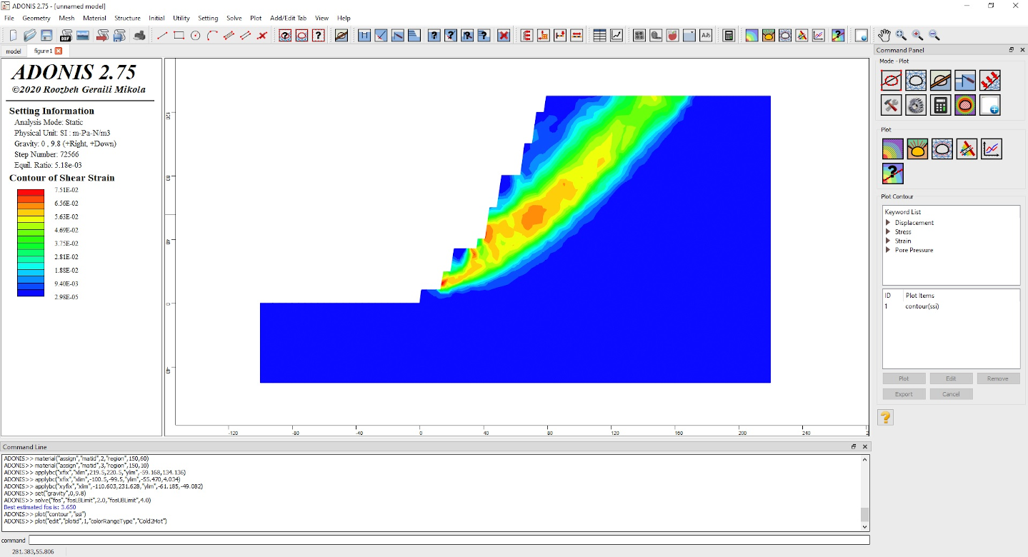
Solve FOS: ADONIS provides an automatic factor-of-safety solution using the Strength Reduction Method (SRM) that can be used for stability analyzes of models. The SRM progressively reduces the shear strength of the material to bring the model to a state of limiting equilibrium. The automated method can be applied to the Mohr-Coulomb and Hoek-Brown material models.
Solve Relax: Force on the boundary of excavation will be reduced to a prescribed level, to simulate 3D effect of a tunnel advance. This reduction of the force will happen gradually during predefined number of steps to avoid a large tensile stress in the element which might cause by the excavation
The Shear Strength Reduction module in ADONIS allows you to automatically perform a finite element slope stability analysis, and compute a critical strength reduction factor for the model. The critical strength reduction factor is equivalent to the "safety factor" of the slope.
There are several different types of structural elements to operate effectively in a range of ground conditions.
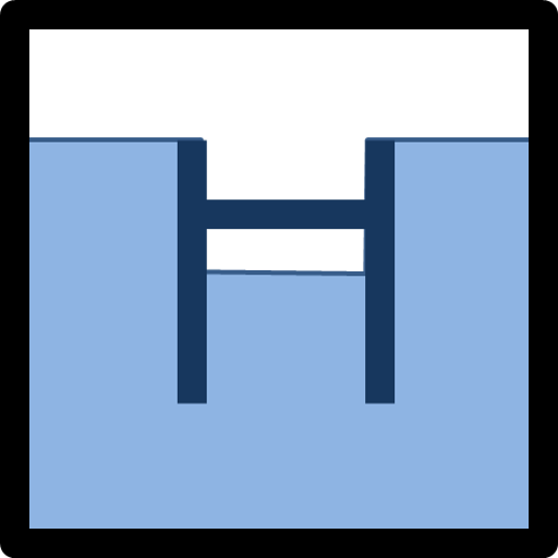 |
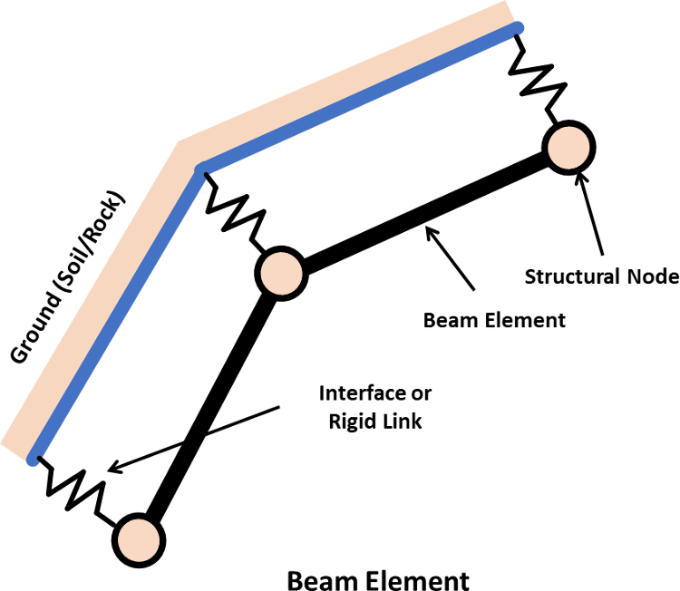
Beam Element: Beam elements are two-dimensional elements with three degrees of freedom (x-translation, y-translation and rotation) at each end node. Beam elements can be joined together with one another and/or the node. Interface elements can be attached on both sides of beam elements in order to simulate the frictional interaction of a foundation wall with a soil or rock. |
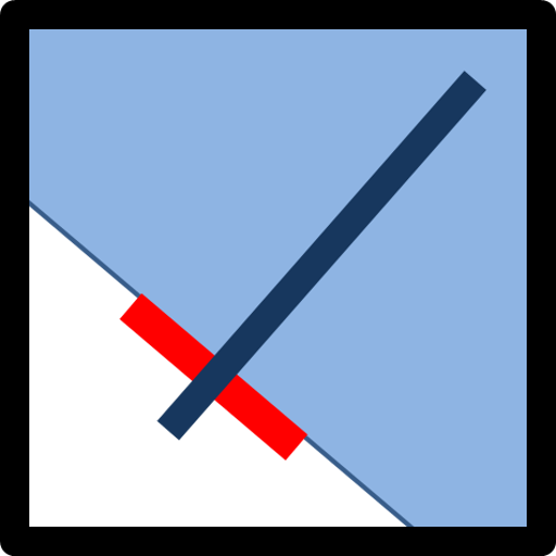 |
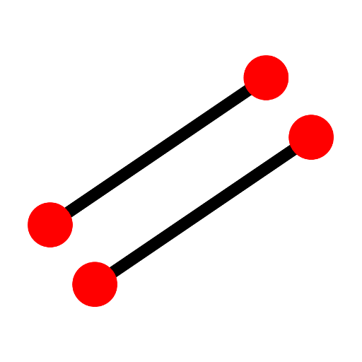
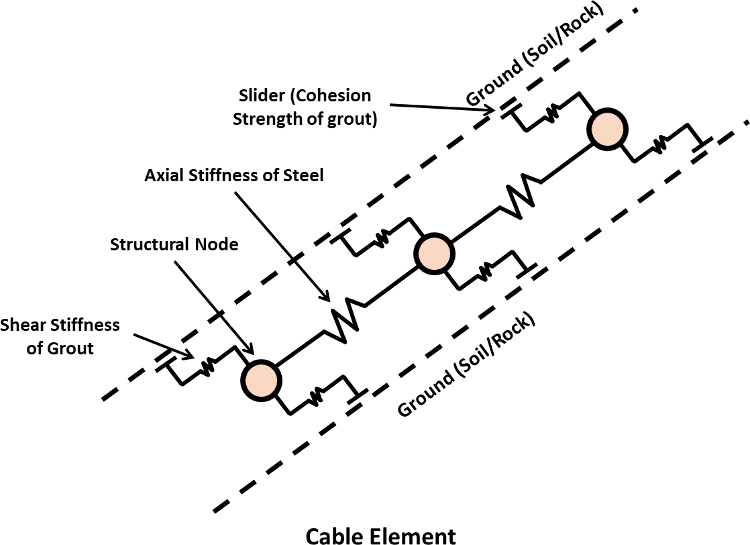
Cable Element: Cable elements are one-dimensional axial elements that may be grouted so that the cable element develops forces along its length as the finite element mesh deforms. Cable elements can yield in tension or compression, but they cannot sustain a bending moment. If desired, cable elements may be initially pretensioned. |
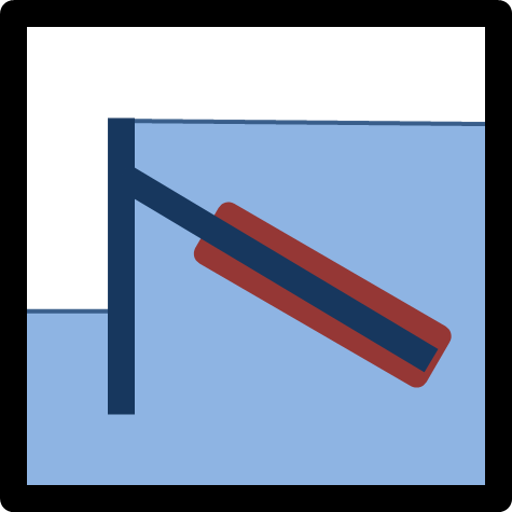 |
Tieback Element: The Tieback bolt represent the behavior of grouted tieback support. Tieback element uses the same formulation as the Cable Element, with allowance for an unbonded length. |
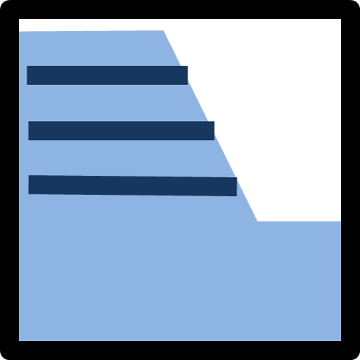 |
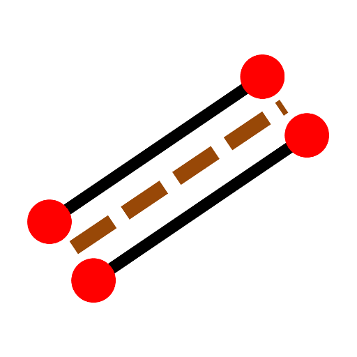
Strip Element: Strip elements represent the behavior of thin reinforcing strips placed in layers within a soil embankment to provide structural support. The strip element is similar to the cable element, in that strips can yield in tension or compression, and a tensile failure strain limit can be defined. Strips cannot sustain a bending moment. Strip elements are designed to be used in the simulation of reinforced earth retainingwalls. |
A scripting language embedded within ADONIS that enables the user to define new variables and functions. These functions may be used to extend ADONIS’s capabilities or add user defined features (e.g., servo-control boundaries may be applied to a numerical test, unusual property distributions specified, and parameter studies automated).
The ADONIS user interface provides a complete interactive modeling environment, project management facilities, a built-in library of materials, easy specification of boundary conditions and structural elements, extensive plotting capabilities, and run-time monitoring of results.
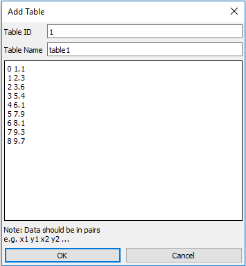
Tables
Tables are convenient data structures consisting of a number of x,y pairs. Tables may be plotted, imported and exported as ASCII data files. Tables can be used in ADONIS to vary friction, cohesion, dilation, tensile strength with accumulated plastic strain for the strain-softening model;
Histories
Histories are recordings of displacements, strains and stresses at a user-defined location (some node, element). By default histories are recorded every 10 calculation cycles, but this can be selected by the user. A time history of as many as 500 variables can be made in one run. Histories may be plotted (versus time, steps or another history), converted to Tables and exported as an ASCII data file.